Last updated:
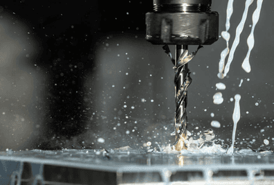
Radiographic testing is a non destructive testing method that uses ionizing radiation to reveal the internal structure of a component without damaging it.
By passing X rays or gamma rays through a material, you can capture an image of what is beneath the surface.
Internal defects like cracks or voids that are completely invisible to the naked eye become visible on the resulting radiograph.
Picture a large steel casting that looks absolutely perfect on the surface. The finish is smooth, the dimensions are within a tolerance of ±0.1 mm, and visually, it seems flawless. Then it fails catastrophically under load.
Few things are more baffling, or dangerous, than a part that looks intact on the outside but hides fatal flaws inside. You’re left staring at the broken pieces, wondering what went wrong.
The most dangerous defects are in reality often hiding deep below the surface where your callipers and gauges simply can’t reach.
To truly verify structural integrity, you need a way to see through solid materials just like a doctor looks at a broken bone.
This is the core purpose of radiographic testing. It relies on the principle that radiation passes through matter but is absorbed differently depending on the material’s density and thickness.
This post covers a complete guide to the radiographic testing procedure. It explains why this method is the industry standard for weld inspection and casting examination.
We will also compare the two distinct radiation sources available (X-ray generators and gamma ray isotopes) so you understand which distinct source is right for your specific application.
Here is what you need to know.
Table of Contents
Film Radiography Technique
If you have ever broken a bone and looked at that spooky black-and-white sheet on a light box, you have seen film radiography in action.
While the industry is moving rapidly toward digital sensors, strictly analog film remains the oldest and most established technique for image acquisition in non-destructive testing.
There is a reason it has stuck around for so long: it works reliably, and it provides a heavy, physical permanent record that auditors love.
But getting a clear image is deceptively complex. It is not just “point and shoot.”
You are essentially painting with radiation, using radiographic film to capture a latent image, an invisible chemical change on the film that only appears after processing.
The concept relies on differential absorption. When you shoot radiation through a weld, a solid section absorbs more energy than a section with a crack or void.
The radiation that passes through hits the silver halide crystals in the film emulsion. Areas receiving more radiation (like voids) turn darker upon development, while denser areas appear lighter. Interpreting these varying densities is how you spot the flaw.
Before wasting expensive film on a part, you should always inspect the surface condition first. As detailed in our guide on visual testing implementation, removing surface irregularities beforehand prevents false indications on your radiograph.
Film Selection and Handling
You cannot use just any film for industrial parts. Film is classified by systems like ISO 11699-1 based on speed and grain size. Here is the trade-off you need to manage:
- Fine-grain film (slower speed) yields very sharp images but requires longer exposure times.
- Coarse-grain film (faster speed) cuts down your radiation time but produces “noisier” images with less definition.
To protect this sensitive media, you must load the film into a light-tight holder or cassette. This is usually done in a darkroom or a changing bag.
Any accidental exposure to visible light will fog the film and ruin your inspection data.
Verifying Quality with IQIs
How do you prove that your exposure was actually sensitive enough to see a hairline crack? You use an Image Quality Indicator (IQI), often called a penetrameter.
This is a small device (usually a plaque with holes or a series of wires) placed on the source side of the part during the exposure.
When you view the developed film, you must be able to see the specific wires or holes on the IQI that correspond to your required sensitivity (often 2% of the material thickness).
If the IQI is not visible on the radiograph, the inspection is invalid, regardless of whether the weld looks good or bad. It is your proof of calibration.
Darkroom Processing Requirements
Creating the latent image is only half the battle. You then have to make it visible through chemical processing. This typically happens in a strictly controlled darkroom environment or an automatic processor.
The process follows a strict sequence:
- Developing: Converts the exposed silver halide crystals into metallic silver (the black parts of the image). Temperature control here is critical; a variance of just 1°C can shift film density significantly.
- Stop Bath: Halts the development process immediately to prevent over-developing.
- Fixing: Removes the unexposed crystals, making the image permanent and light-safe.
- Washing and Drying: Removes residual chemicals so the film can be stored for years without degrading.
Under standards like ISO 11699-2, you must monitor your chemical activity constantly. If your developer is too weak or too cold, you might miss a defect simply because the film contrast was too low to show it.
Film Archival and Storage
One of film’s key advantages is its role as a permanent legal record. But maintaining that record requires proper storage conditions.
Under ISO 11699-2, archival film must be stored in a controlled environment with relative humidity between 30% and 50% and temperatures below 21°C (70°F). Improper storage can cause the emulsion to deteriorate, fading the image over time.
Retention periods vary by industry and application. Nuclear power plants typically require radiographs to be retained for the life of the plant plus decommissioning, often 50 years or more.
Pressure vessel records under ASME codes are commonly kept for 10+ years. Pipeline inspections per API 1104 may require retention for the operational life of the line.
Always verify the specific retention requirements in your applicable code or contract before disposing of any inspection records.
Now that you understand how to capture and develop a radiographic image, let us examine the two types of radiation sources available to you.
Gamma Ray vs X-Ray Sources
Choosing between X-ray and gamma ray sources usually comes down to a trade-off between control and portability.
While both methods use ionizing radiation to penetrate materials, the way they generate that radiation is fundamentally different. X-rays are machine-generated using electricity, meaning you can adjust the intensity. Gamma rays come from natural nuclear decay of isotopes.
For a technical breakdown of these methods, the ASNT’s guide to radiographic testing methodology is a reliable resource.
X-Ray Radiation
X-ray systems work by accelerating high-speed electrons inside a vacuum tube. When a high electrical current forces these electrons to slam into a tungsten target, their kinetic energy converts into X-ray photons and heat.
The massive advantage here is adjustability. You can fine-tune the voltage (kV) and amperage (mA) to match the specific thickness of your part.
Standard industrial units typically operate between 160 kV and 450 kV. Because they require a high-voltage power supply and cooling systems, X-ray sets are generally heavier and less portable than their gamma counterparts.
They are ideal for shop environments where power is readily available.
Unlike gamma sources, an X-ray tube is safe when unpowered. Once you cut the electricity, the radiation stops instantly.
| Factor | X-Ray | Gamma Ray |
|---|---|---|
| Power source | Electrical (adjustable) | Radioactive decay (fixed) |
| Portability | Limited (needs power) | High (no cables) |
| Safety control | Off when unpowered | Always emitting |
| Typical steel thickness | Up to 75 mm (at 450 kV) | 10–180 mm (varies by isotope) |
| Image quality | Higher contrast, sharper detail | Lower contrast, larger focal spot |
| Common sources | 160–450 kV tubes | Ir-192, Se-75, Co-60 |
| Source decay | N/A (machine-generated) | Ir-192: 74 days; Co-60: 5.3 years |
| Regulatory burden | Moderate (electrical safety) | High (radioactive materials license) |
| Best for | Shop environments | Field inspections |
Gamma Ray Radiation
Gamma rays come from radioisotopes, unstable atoms that emit radiation as they decay to a stable state. The most common industrial isotopes are Iridium-192, Selenium-75, and Cobalt-60.
Unlike X-ray tubes, you cannot turn these sources off. They are “always on,” which requires strict safety protocols and heavy shielding containers.
The main benefit is portability. Since there are no power cords or cooling lines, you can use them in remote locations.
Cobalt-60 is particularly powerful, emitting energies at 1.17 MeV and 1.33 MeV, which allows it to penetrate thick steel sections that would stop a standard X-ray beam.
Radiographic Testing Procedure
Performing a successful inspection is not just about pointing a ray source at a pipe and hoping for the best. To get accurate results, you must follow a strict radiographic testing procedure.
Because you are capturing a shadow image of internal structures, even a small error in geometry or timing can hide a serious defect.
The workflow breaks down into five steps: aiming the radiation source, placing the film or detector, exposing the part, processing the data, and examining the resulting image.
There is a catch, though: you can’t fix a bad setup in post-processing. Steps like source positioning and exposure calculation happen before you ever capture an image.
If these aren’t done correctly, you might produce a radiograph that looks clear but fails to show cracks or voids. That is why proper setup is the single most important part of the entire process.
Pre-Inspection Preparation
Before you even unlock the exposure device, you need to perform a thorough visual examination of the part. A common misconception is that X-rays will just “look through” surface mess, but it turns out that surface irregularities like weld spatter or rough grinding marks can show up as confusing artifacts on your final image.
To avoid this, you may need to grind the surface flush or remove coatings that could interfere with the interpretation.
You also need to assess the physical access. Radiography usually requires access to both sides of the component (one for the source, one for the detector). If you can’t reach the back of a weld to place the film, you might need to change your technique entirely.
Finally, you must create a detailed inspection plan. This documentation records exactly how you intend to shoot the part, making the test repeatable by another technician later.
Source and Detector Positioning
Geometry is everything here. You must direct the radiation beam to the exact center of the section you are examining. Ideally, the beam should be normal (perpendicular) to the material surface.
If the beam hits the part at an angle, the image of any internal defect will be distorted or shifted, making it much harder to evaluate its size. Special techniques exist for specific geometries, but 90 degrees is the standard goal.
You also need to worry about the thickness variation across your image. We follow the 6% rule: the thickness of the material at the edges of your diagnostic area shouldn’t exceed the actual thickness at the center by more than 6%.
If it does, the density of the image will vary too much to be readable. You place the film cassette or detector directly opposite the source, as close to the object as possible to reduce geometric unsharpness.
Exposure and Processing
Calculating the exposure time is deceptively complex. It depends on the source strength (Curie or kV), the distance to the film, and the material density.
Unlike a digital camera that snaps instantly, radiographic film has a cumulative response. It soaks up radiation over time, meaning thicker steel requires a significantly longer exposure than thin aluminum.
For example, consider inspecting a 20 mm steel weld using an Iridium-192 source with an activity of 50 Curies. At a source-to-film distance (SFD) of 700 mm, using Class C5 film with lead screens, you would typically need an exposure of approximately 3-4 minutes.
Double the steel thickness to 40 mm, and that exposure jumps to roughly 12-15 minutes. These values are derived from manufacturer exposure charts, which plot material thickness against exposure factor (Curie-minutes or mA-minutes) for specific source-to-film distances.
Once the exposure is complete, you process the media. For traditional film radiography techniques, this happens in a darkroom. You run the film through a chemical development process to reveal the latent image.
You typically view the final result as a negative. Darker areas represent more radiation passing through (less density), while lighter areas indicate thicker or denser material. You don’t usually print these as positives, you interpret the negative directly using a high-intensity viewer.
Film has served the industry well for decades. But what if you could skip the darkroom entirely?
Digital Radiography Methods
While film has been the industry standard for decades, digital radiography methods are rapidly becoming the preferred choice for many NDT technicians.
Think of this shift like moving from an analog film camera to a modern DSLR.
You stop worrying about darkrooms and chemicals and start focusing entirely on the image quality and analysis. The most immediate benefit you will notice is speed.
Because you remove the need for chemical film processing, the time between exposure and interpretation drops significantly. You also gain the ability to digitally store and share files without large physical archives.
Perhaps most importantly, digital images offer a wider dynamic range. This means you can adjust the brightness and contrast on your monitor to reveal defects that might be invisible on a standard film radiograph.
In many cases, this allows for shorter exposure times, improving safety and efficiency.
Computed Radiography
Computed Radiography (CR) often feels like a bridge between the old and the new. In this method, you replace the traditional film with a reusable phosphor imaging plate housed in a cassette.
The workflow looks very similar to film radiography: you place the cassette behind the part, expose it to radiation, and then take it to a processing station.
The difference happens inside the plate. Instead of a chemical reaction, the phosphor layer stores the radiation energy as a latent image. You then feed the plate into a specialized laser scanner. The scanner reads the stored energy and converts it into a digital signal, creating your image on a computer screen.
The best part is that you can erase the plate using intense light and reuse it thousands of times. While it requires an extra scanning step compared to direct methods, CR is often more cost-effective and the flexible plates can fit into tight spaces where rigid detectors cannot.
Direct Radiography
If you need speed above all else, Direct Radiography (DR) is usually the answer. This technique skips the intermediate scanning step entirely.
You use a flat panel detector (often called a Digital Detector Array or DDA) that connects directly to your computer workstation. When the radiation hits the detector, it is converted immediately into an electrical charge and then a digital image.
The image appears on your screen in near real-time, often within seconds of the exposure. This makes DR highly efficient for high-volume manufacturing environments.
The image quality is typically superior to CR, offering better signal-to-noise ratios. But there is a catch: the panels are rigid, fragile, and significantly more expensive than phosphor plates. You generally use DR for applications where the detector can be positioned easily and where cycle time is critical.
Computed Tomography
Sometimes, a 2D image just isn’t enough. Standard radiography flattens a 3D object into a 2D shadow, which causes a problem known as superimposition. Structures on the front of the part hide defects on the back.
Computed Tomography (CT) solves this by taking hundreds, or even thousands, of radiographic exposures as the part (or the source) rotates 360 degrees.
A powerful computer then reconstructs these images into a full 3D volumetric model. This allows you to virtually “slice” through the object from any angle.
You can inspect complex internal geometries, measure wall thicknesses precisely without cutting the part, and locate the exact depth of a void or crack. While CT equipment is a major investment and generates massive data files, it provides a level of geometric accuracy that no other radiographic method can match.
Cost and Investment Considerations
When planning your radiography program, understanding the relative costs of each method helps you make informed decisions.
Film radiography has low upfront equipment costs but high ongoing expenses. Each sheet of film is single-use, and you must maintain darkroom facilities and chemical supplies. Over thousands of exposures, consumable costs add up significantly.
Computed Radiography (CR) represents a middle ground. The initial investment in a scanner and plates is moderate, but since phosphor plates can be reused for 1,000+ exposures, your per-shot consumable cost drops dramatically compared to film.
Direct Radiography (DR) requires the highest upfront investment. Flat panel detectors can cost several times more than CR systems, but DR offers the lowest per-shot cost and fastest throughput. For high-volume inspection operations, DR often pays for itself within a few years through reduced labor and consumable expenses.
Computed Tomography (CT) is the most capital-intensive option, with systems costing significantly more than conventional radiography setups. But for complex parts requiring full volumetric analysis, CT can reduce overall inspection time by eliminating the need for multiple conventional shots from different angles.
Interpreting Radiographic Images
Capturing a radiograph is only half the job. The real skill lies in interpreting what you see.
A radiograph is essentially a shadow map of density variations inside the material. Learning to recognize defect signatures takes training and experience, but understanding the basics will help you appreciate what qualified interpreters are looking for.
Film Density and Viewing Conditions
Before evaluating any defects, you must verify that the radiograph itself meets quality requirements. You measure film density using a calibrated densitometer.
Most codes require the density in the area of interest to fall between 2.0 and 4.0 (on the optical density scale). If the film is too light (underexposed) or too dark (overexposed), subtle defects become invisible.
Viewing conditions matter equally. You should evaluate radiographs on a high-intensity illuminator (film viewer) in a darkened room. Ambient light washing out the viewer makes it nearly impossible to see low-contrast indications.
For digital images, your monitor should be calibrated per ASTM E 2698 or equivalent, with appropriate brightness and contrast settings.
Common Defect Appearances
Different defects produce characteristic patterns on a radiograph. Learning to recognize these signatures is fundamental to accurate interpretation.
- Porosity: Appears as small, rounded dark spots (gas pockets are less dense than surrounding metal). Scattered porosity looks like random dots; cluster porosity groups in localized areas; linear porosity aligns along the weld direction.
- Slag inclusions: Show as irregular dark shapes, often elongated along the weld axis. Unlike porosity, slag inclusions have uneven edges and may appear in chains between weld passes.
- Lack of fusion: Appears as a dark linear indication along the weld edge or between passes. It indicates the weld metal did not properly bond with the base metal or previous pass.
- Incomplete penetration: Shows as a dark line at the weld root, indicating the weld did not fully penetrate through the joint thickness.
- Cracks: Appear as fine, dark irregular lines with sharp edges. Cracks can be longitudinal, transverse, or branching (star cracks). They are typically the most critical defects.
- Undercut: Shows as a dark groove along the edge of the weld cap where base metal has been melted away without adequate fill.
Acceptance Criteria Basics
Not every indication means rejection. Applicable codes and standards define acceptance criteria that specify what size, type, and distribution of defects are permissible. For example, ASME BPVC Section VIII has different acceptance standards than AWS D1.1 for structural steel or API 1104 for pipelines.
Generally, cracks are never acceptable regardless of size. Rounded indications like porosity may be acceptable if they fall within size and spacing limits defined by the code. Linear indications like lack of fusion are typically more restricted.
The interpreter must measure each indication, compare it against the applicable acceptance table, and make a disposition: accept, reject, or repair.
Only Level II or Level III certified personnel should interpret radiographs and sign inspection reports. Misinterpretation can lead to either unnecessary repairs (costly) or missed defects (dangerous).
Weld Inspection Exposure Arrangements
Setting up the geometry for a shot is often the trickiest part of the radiographic testing procedure. You cannot simply aim the radiation source at a weld and expect a clear image.
You have to consider the geometry of the part, your access to it, and where the film or detector sits relative to the source. If you get this wrong, the geometric unsharpness might hide the very cracks you are looking for.
The arrangement you choose effectively determines how the radiation passes through the material. In industrial radiography, we categorize these setups into two main buckets: Single-Wall Exposure (SWE) and Double-Wall Exposure (DWE).
Your choice depends entirely on whether you can practically reach both sides of the component. For example, inspecting a large storage tank is very different from checking a small-bore pipe where you cannot physically fit a source inside.
Panoramic Exposure
This is the “gold standard” for cylindrical objects like pipes, tanks, or pressure vessels.
In a panoramic exposure, you place the radiation source (usually a gamma ray source like Iridium-192 due to its portability) directly in the geometric center of the cylinder. You then wrap the film or detectors around the entire outside circumference of the weld.
This setup creates a Single-Wall Exposure / Single-Wall View (SWE/SWV). Since the source is in the middle, the radiation travels through the steel wall only once before hitting the film. The result is a uniformly dense image of the entire weld seam in a single shot.
It is far more efficient compared to taking multiple exposures from the outside. The catch is obvious: you must have access to the interior of the pipe or vessel to position the source accurately.
Contact and Elliptical Shots
When you cannot access the inside of a pipe (which is common for small diameter piping), you have to shoot through the pipe from the outside. This is a Double-Wall Exposure (DWE).
The radiation beam penetrates two walls of the pipe, but usually, we only evaluate the image of the wall closest to the film. This describes the classic Double-Wall Exposure / Single-Wall View (DWE/SWV) arrangement.
For slightly different visuals, you can use the elliptical technique. Here, you offset the source slightly from the perpendicular axis. On the resulting film radiography technique, the circular weld appears as an ellipse.
This separates the images of the top and bottom welds on the film so they do not overlap directly. It is particularly useful for small-bore piping where you want to inspect both walls in a single view, though it requires precise alignment so the source-side weld does not obscure the film-side weld.
Radiographic Testing Equipment
When you start setting up an inspection, you quickly realize that Radiographic Testing (RT) isn’t just about having a powerful camera. It is a complete ecosystem of tools designed to generate, control, and capture ionizing radiation safely.
At its core, every RT setup requires four essential components: a radiation source to penetrate the part, an exposure device to house that source, imaging media to record the result, and most importantly, safety equipment to keep you alive.
You generally have two system categories to choose from: stationary or portable. Stationary systems are typically large X-ray vaults found in factories. They offer excellent control and resolution because they run on stable electrical power.
But you can’t exactly drag a massive X-ray tube up a pipeline. That is where portable systems come in. These usually rely on gamma ray sources (isotopes) housed in heavy shielding. They sacrifice some image sharpness and safety control for the ability to shoot shots in the middle of nowhere.
Your choice of equipment largely depends on the density and thickness of what you are inspecting.
If you need to verify a thick steel casting, you need the high-energy punch of a Cobalt-60 source. If you are checking thin aluminum welds, a lower voltage X-ray tube gives you the contrast sensitivity you need to spot fine cracks.
Radiographic Cameras
In photography, the camera captures the light. In radiography, the “camera” is actually the device that holds and releases the radioactive source. It is effectively a shielded container that acts as a projector.
The most common type you will encounter in the field is the projector design. These devices store the radioactive isotope in a depleted uranium or tungsten shield block when not in use.
To make an exposure, you use a crank mechanism and drive cables to push the source out of the shield, through a guide tube, and into the exposure position (often called the collimator).
This design uses an S-shaped channel within the shield block. This shape prevents radiation from beaming straight out when the source is in the stored position.
Alternatively, some older or specialized systems use a shutter design, where a massive door manually opens to reveal the source. While simple, these require you to be closer to the device, which makes safety distance harder to manage.
Detectors and Sensors
On the other side of your part, you need something to catch the shadows. Traditionally, this was always silver halide film. It works exactly like old-school photography film: it is sensitive to radiation, requires chemical development, and produces a physical negative.
Film is still widely used because it offers very high spatial resolution and creates a hard-copy legal record.
Modern inspections are moving toward digital detectors. You might use Phosphor plates (for Computed Radiography), which trap radiation energy and are later scanned by a laser to release a digital image.
Or, for immediate results, you can use Flat Panel Detectors (for Direct Radiography). These convert radiation directly into an electrical signal, giving you a view of the internal structure in near real-time. While flat panels are expensive and fragile, they dramatically speed up the workflow by eliminating chemical processing times.
Safety Requirements
Working with radiation is deceptive. You cannot see, smell, or feel the energy passing through the material (and potentially you). That is why safety is the single most important aspect of radiographic testing.
Before you even touch a camera or source, strictly adhering to Ionising Radiation Regulations and your site-specific local rules is non-negotiable.
Because the consequences of errors are severe, inspectors require operating licenses issued by state and federal agencies. You must operate under a strict framework designed to protect both you and the public from radiation hazards.
Effective protection relies on three fundamental principles: Time, Distance, and Shielding.
Minimizing time near the source reduces total exposure. Distance is your ally because radiation intensity drops sharply following the inverse square law. Appropriate shielding between you and the source absorbs the energy before it reaches you.
Personnel Safety Equipment
You cannot rely on your senses to detect radiation, so you must use specialized instrumentation. A helpful way to understand these devices is to compare them to a car dashboard.
First, you have the radiation survey meter (such as a Geiger-Müller counter). This acts like a speedometer. It measures the exposure rate at your current location in real-time.
This allows you to verify the boundaries of the controlled area and confirms you are not standing in a “hot” zone.
Next is the alarming dosimeter. Think of this as your tachometer or “redline” indicator.
If the radiation level exceeds a preset threshold, it triggers a loud alarm to warn you immediately. This device prevents you from inadvertently walking up to an exposed source.
Finally, you wear a film badge or thermoluminescent dosimeter (TLD). This serves as the odometer. It records your cumulative exposure over a longer period, usually a month. These are processed by a third party to verify your total dose remains within valid legal limits.
Standard procedure requires radiographers to work in pairs. If an accident occurs or a source fails to retract, the second person provides the necessary support to secure the area and execute emergency procedures.
Shielding Materials
The material you use to block radiation depends heavily on the radiation type and its energy. High-density materials are required to stop the penetrating power of gamma rays and X-rays.
Lead is the industry standard for shielding. It is used in sheets, blocks, or “shot” (bags filled with lead pellets) to wrap around components or collimators.
For situations requiring even higher density, you might use depleted uranium or tungsten. In large stationary bunkers, thick concrete or sand serves as effective structural shielding.
Shielding is especially critical for gamma sources. Unlike an X-ray tube, which you can turn off by cutting the power, a radioactive isotope is always on. It emits radiation continuously through radioactive decay.
So the source must be housed in a heavily shielded exposure device (camera) whenever it is not being used for an exposure.
For more detailed information on global safety standards, you can refer to the resources provided by the IAEA radiation safety standards.
Personnel Certification Levels
Not everyone performing radiography has the same authority. Under ASNT SNT-TC-1A (the most widely adopted certification standard in North America), NDT personnel are qualified at three distinct levels based on training, experience, and demonstrated competence.
- Level I: Performs specific calibrations, tests, and evaluations under direct supervision. A Level I technician can set up equipment and acquire radiographs but cannot interpret results or sign off on inspection reports.
- Level II: Works independently to set up and calibrate equipment, perform inspections, and interpret results according to applicable codes and standards. Level II personnel can prepare written procedures and train Level I technicians.
- Level III: The highest qualification. Responsible for establishing techniques, interpreting codes and standards, designating methods and procedures, and certifying Level I and II personnel. A Level III can authorize the use of new techniques and resolve disputes about inspection results.
European and international frameworks follow a similar structure under ISO 9712. Regardless of which standard applies, the key principle remains: only appropriately certified personnel should perform, interpret, or supervise radiographic inspections.
Industry Applications
Radiographic testing is essentially the “eyes” of the industrial world. It is valued across distinct sectors because it allows us to detect internal defects without damaging the component itself.
Whether we are checking a welded pipe or a turbine blade, RT provides the definitive proof needed for safety and regulatory compliance. The ability to see subsurface flaws makes it indispensable for verifying the quality of critical infrastructure.
Energy and Petrochemical
In the oil and gas industry, maintaining containment is the primary goal.
Technicians use RT to inspect miles of pipelines, large storage tanks, and complex offshore structures for signs of localized corrosion or weld flaws. These inspections are often mandated to prevent environmental hazards.
It is also a strict requirement for nuclear power plants. Inspecting pressure vessels and valves verifies they can withstand extreme operating conditions without failure, keeping both the facility and the public safe.
Aerospace and Manufacturing
In aviation, structural failure is simply not an option. Manufacturers use X-ray inspection and computed tomography to verify the integrity of critical aircraft engines and airframe components.
It is equally important in general manufacturing for checking automotive components, such as chassis welds and engine parts.
With the rise of additive manufacturing (3D printing), RT has found a new home. It is one of the few ways to confirm the dimensional accuracy and material density of complex printed parts that are otherwise impossible to measure internally.
Radiographic Testing vs Other NDT Methods
How does radiographic testing compare to other non-destructive examination methods? Each technique has its strengths.
Ultrasonic testing excels at measuring thickness and finding planar defects but requires direct surface contact. Magnetic particle testing works only on ferromagnetic materials and detects surface or near-surface flaws. Dye penetrant testing reveals surface-breaking cracks but cannot see internal defects at all.
Radiography stands out because it provides a permanent visual record of internal structures. You can archive radiographs for decades and re-interpret them if questions arise.
RT does require strict safety protocols due to ionizing radiation, making it more complex to deploy than surface methods. For critical welds and castings where internal integrity is paramount, radiographic testing remains the definitive choice.
Applicable Standards
One of the trickiest parts of NDT is knowing exactly which rulebook to follow.
You can have the best X-ray source and the sharpest detector, but if your technique does not strictly follow the agreed-upon standard, your results are technically invalid. These documents are not just suggestions; they act as the precise recipe for capturing an image that legally counts.
For international projects, you will usually reference ISO standards. The general rules for metallic materials are found in ISO 5579.
When you are inspecting welds specifically, use ISO 17636-1 for traditional film and ISO 17636-2 for digital detectors. If you rely on film, you must also check ISO 11699-1 and ISO 11699-2 to legally classify your film systems.
In North American industries, the requirements often shift to ASTM or ASME. ASTM E 94 is the standard guide for general examination, often paired with ASTM E 1032 for weldments.
For pressure vessels, you must adhere to ASME BPVC Section V, Article 2. Finally, if you are working on pipelines, API 1104 is the standard that governs radiographic testing procedure validity.
Conclusion
We have covered quite a bit of ground here. We started by defining Radiographic Testing as a non-negotiable method for seeing exactly what is happening inside your materials without slicing them open.
Whether you use electrical X-ray tubes for controlled manufacturing environments or portable gamma ray isotopes for remote field work, the goal remains the same: capturing internal defects that would otherwise go unnoticed until a component fails.
We also looked at the tools of the trade. While film radiography techniques remain a reliable standard for many industries, the shift toward digital radiography methods is undeniable.
It turns out that moving to systems like Computed Radiography or Direct Radiography isn’t just about speed. It allows for advanced image enhancement, easier archives, and lower chemical waste.
If there is one section worth revisiting, it is the guidance on safety requirements. Working with ionizing radiation is serious business.
You need to strictly respect the three pillars of protection: time, distance, and shielding. No inspection result is worth compromising the health of the operator or the public, which is why personnel certification and strict adherence to regulations are absolute musts.
Key Takeaway: The quality of your results relies entirely on proper technique selection and geometry. Even the most expensive digital detector cannot fix a blurry image caused by poor source-to-object distance.
So, where do you go from here? Don’t try to guess your exposure parameters. Always consult the applicable standards, such as ISO 17636 or ASME BPVC Section V, and verify your plan with a qualified Level III technician.
As automation continues to improve, keep an eye on how AI-assisted defect recognition might fit into your workflow in the future.
This breakdown should help you feel more confident about adding radiography to your quality assurance toolkit. It is a tricky but remarkably powerful method when executed correctly.
Stay safe and happy testing!
Frequently Asked Questions
What is radiographic testing and how does it verify quality? Radiographic testing (RT) is a non-destructive inspection method using X-rays or gamma rays to reveal internal defects. Radiation passes through materials differently based on density, creating shadow images that show cracks, voids, and porosity invisible to the naked eye.
What types of defects can you find with radiography?
You can use this method to detect internal flaws like cracks, porosity, and voids. It identifies volumetric changes inside welds, castings, and forged parts. Radiography reveals both surface and subsurface defects, allowing you to catch structural issues that visual inspections miss.
What is the main difference between X-rays and gamma rays?
The difference lies in how the radiation is produced. X-ray tubes generate radiation electronically using high voltage, which allows you to adjust intensity. Gamma rays come from radioactive isotopes like Iridium-192. These sources do not need electrical power, making them more portable but harder to shield.
Why do operators need specific safety equipment for radiography?
Ionizing radiation is hazardous to human health. Because you cannot see or feel it, safety gear is mandatory. Operators use survey meters to measure exposure rates and personal dosimeters to track cumulative dose. Proper shielding and maintaining distance are the primary ways you protect yourself from harmful exposure.
How does digital radiography differ from standard film methods?
Digital radiography uses reusable plates or flat panel detectors instead of chemical film. This eliminates the need for darkroom processing and lets you view images almost instantly on a screen. While film offers very high resolution, digital methods provide faster results and simpler data storage for your inspection records.
When should you choose gamma rays over X-ray sources?
You typically choose gamma rays for field inspections where electrical power is unavailable or site access is difficult. Isotopes like Iridium-192 work well for penetrating thick steel sections in remote locations. But these sources cannot be turned off, so handling and storage require strict safety protocols.
How does source geometry affect the sharpness of the image?
A smaller source size creates a sharper image by reducing geometric unsharpness. If the radiation source is too large or placed too close to the object, defect edges will look blurry on the final image. You must calculate the optimal distance to ensure the radiograph is clear enough to interpret accurately.
Why are Image Quality Indicators required for every shot?
An Image Quality Indicator (IQI) proves the radiograph has sufficient sensitivity to reveal defects. You place these wires or plaques on the source side of the part before exposure. If you can clearly see the required wire or hole on the final image, the test quality meets the standard.
What defines a double-wall exposure in weld inspection?
A double-wall exposure shoots radiation through both walls of a pipe or vessel. You use this technique when you cannot access the inside to place film. Depending on the specific setup, the resulting image allows you to view both walls simultaneously or just the wall closest to the detector.