Last updated:
Welding quality control is a set of processes that ensure weld integrity and compliance with standards.
These steps help you prevent defects and guarantee safe, reliable joints in every project.
The welding quality detection market reached USD 1.2 billion in 2024 and will grow to USD 2.5 billion by 2033 at an 8.5% compound annual growth rate.
Pretty impressive, isn’t it?
This rise shows how import quality has become in mechanical engineering, as it boosts safety and efficiency in every application fields.
Many engineers face challenges when they are trying to identify issues through, for exemple, visual inspection techniques or non destructive testing strategies.
In this article, we will explore weld quality standards, welding defect detection methods, and practical tools to maintain high standards. You will learn how to apply these in your real life, daily work for better results.
Here we go.
Table of Contents
What is Welding Quality Assurance?
Let us focus on the core concepts of quality assurance.
Quality Assurance (or QA) involves preventive steps to monitor and evaluate processes.
It ensures you produce high quality welds from the start. It is kind of likes building safeguards to avoid issues before they appear.
Quality Control, verifies that your welds meet set specifications.
You check and test procedures and final products against clear criteria. This step catches defects through methods like non-destructive testing and visual inspection techniques.
You need QA and QC to meet weld quality standards and regulatory demands.
In the real business world, contracts companies signs almost all the time require compliance with codes for items like pressure vessels and structural steel. These processes prove the sold product or service will meet a certain quality standard minimum.
If you don’t do these procedures, and you make your product or service exposed to risks. In worst cases, poor quality welds can lead to accidents or disasters.
You don’t want to be responsible for such things. Nobody wants.
Technical Documentation
Let’s focus our attention to the technical documents that guide these efforts.
Here is the ones we will focus on:
- The Quality Assurance Plan serves as your framework for all quality activities. It outlines the timing of checks and tests. It also assigns roles and responsibilities to personnel involved in the process.
- The Welding Procedure Specification details how to perform each weld. It covers the welding process, materials, and parameters like preheat and temperatures. This document ensures consistency and helps with welding defect detection.
- Weld Maps show the location of each weld on the component or part and assign the correct Welding Procedure Specification to every joint. These maps make it easy to track and reference during production, especially on very large projects.
- The Inspection and Test Procedure, records all quality control activities.
All of these documents must comply with weld quality standards. They provide evidence for audits and help identify issues early.
Welding Procedure Specification
The WPS is the detailed “recipe” for a specific weld.
It’s a formal document providing clear set of instructions to the welder to ensure consistent and high quality results.
Key Information in a WPS:
- Preheat and Post Weld Heat Treatment: Any required heating procedures,
- Base Materials: The type and thickness of metal being joined,
- Welding Process: The method used (SMAW, GMAW, TIG, etc.),
- Filler Metals: The specific electrode or wire to be used,
- Joint Design: How the pieces are prepared and fitted together,
- Welding Parameters: Voltage, amperage, travel speed, and gas flow rates,
- Position: The orientation of the weld (is it flat, horizontal, overhead, etc.).
Weld Map
Weld Maps are engineering documents that visually identifies the location of all required welds on a fabricated structure or component.
Its mostly used to assign the correct WPS to each specific joint, ensuring that the proper welding parameters are used correctly.
It’s usually a technical drawing kind of document that match unique identifiers (looking like W-01, W-02) of every location requiring a weld (connection, fillets, etc.) to the corresponding WPS (WPS-01, etc.).
For exemple.
When you see the W-62/WPS-3156 pair, you directly know that the weld located at W-62, must be done using WPS-3156.
Some maps doesn’t give IDs to location as it’s obvious but it might be part of it.
Weld Maps are essential for managing workflow and maintaining consistency, particularly on large or complex fabrications with a large number of joints and multiple welding procedures.
Supervisors use them to track progress, while welders use them as a direct guide for their work.
They create a clear communication channel between engineering, production, and inspection personnel, ensuring all parties are aligned on the procedural requirements for the fabrication.
Quality Controls for Welds Defect Detection
From the initial preparations until the final inspections, you will need to guarantee a strong and reliable weld.
For that, we will have to make inspections at 3 moments :
- Before Welding: Make sure the materials you’re using have papers that prove they are the right kind and strong enough, just like the design asks for.
- During Welding: Keep an eye on how the temperature get before and between your welds, use the correct welding rod and make sure your weld looks good and follows the requirements of the WPS.
- After Welding: Depending on the rules and what the customer wants, you’ll need to check your welds. You might break a test piece to see how strong it is, or use special tools to check the finished part without breaking it, to find any problems and make sure your welds are top quality.
Destructive vs Non-Destructive Testing Methods
You have two options to check your welds.
One way is Destructive Testing. Which is usually not what you want.
The procedure is to intentionally break small pieces of the weld.
For example, you might cut a piece to look at tiny problems under a optical device (microscope, etc.) or you might pull and bend it to see how strong and flexible it is.
Of course, you will keep track of measurements to record at what strength it break, etc.
These tests help make sure your welding steps are correct, but they do ruin the piece you test.
The other way is Non-Destructive Testing, which checks the weld without breaking it.
That’s the ideal solution because if the weld pass the tests, it means you didn’t waste a part for nothing.
This includes simply looking closely at the outside for problems, using a special liquid to find small cracks, or using sound waves (ultrasonic) or special X-rays (radiographic) to find hidden problems inside the weld.
Let’s focus on the most used methods.
Visual Inspection
The main reason visual testing is used everywhere is its simplicity.
It’s inexpensive since it mostly involves your time and expertise or very affordable equipments if we compare to other control methods.
This allows you to spot surface problems quickly, saving you from more expensive repairs down the line when issues are discovered too late.
Of course, this method has its limits.
It’s pretty obvious that the person inspecting the weld will need a complete training, good expertise and good eyesight.
And, also, the big drawback is that you can only see problems visible at the surface of the weld.
Internal defects like lack of fusion deep inside a joint will (probably) be missed. The process is also open to human error, and the inspector must carefully record all findings.
What tools to use ?
For a proper visual inspection, you’ll need a few specialized tools.
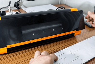
A fillet weld gauge is a primary piece of equipment. This multi tool lets you measure the leg size and throat size of a fillet weld. It also helps you check for concavity, where the weld dips inward, and convexity, where it bulges outward.
Here is what it looks like for reference :

But, before we five in the rest of the tools: remember to keep yourself safe while you are working. While welding, it’s important to wear protective lenses with a shaded pocket viewer for safely observing the arc.
Here are some other items you should have on hand.
- A magnifying glass to get a closer look at the weld surface,
- A flashlight to illuminate the inspection area properly.
- A welding hammer or chisel to remove slag and spatter before you inspect the bead.
- A temperature measuring device, to check preheat, inter pass, and post heat temperatures.
- A tape measure and calipers for general dimension checks.
- A small magnet to help identify the type of material you are working with.
- A caliper for basic measurements.
If you need to zoom in the weld for micron-resolution details inspection, you might need a microscope and impression taking material to reproduce the surface and analyze it.
By the way, Plastiform is very efficient when it comes to identifying porosity or slag inclusions.
But we will cover those a bit later.
Specific Checks for Gas Welds
Gas welding has its own set of visual criteria for a quality weld.
Here is a complete checklist:
- The face should be slightly convex, with reinforcement no more than 1.6 mm above the plate surface.
- The weld should have a consistent width from start to finish.
- The surface should have fine, evenly spaced ripples and be free from excessive spatter.
- The edges should show no signs of undercut or overlap.
- The crater at the end should be filled properly, with no cracks or holes.
A simple destructive test is to bend the upper plate until it is doubled over.
If the root was not properly fused, a crack will open at the joint.
Most Common Weld Defects
Sometimes, things go wrong.
I don’t know a single person in the industry that always succeed first try every weld he made.
These problems are often called weld faults or discontinuities.
Identifying what went wrong is the first step to correcting your technique and making a better weld next time.
Let’s look at some of the most frequent issues you might find in your work.
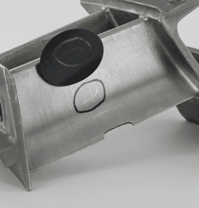
Incomplete Penetration
This defect happens when the weld metal fails to fuse completely with the base metal deep in the joint.
Here is a shot of what it means so you can visualize it clearly:

As you can see, the weld is just sitting on top instead of joining the material all the way through.
This is a serious structural problem.
It occurs in groove welds when metal bridges the gap at the top but leaves an unwelded void at the root.
You can often trace incomplete penetration back to a poor setup or technique. Here are the common reasons:
- The included angle of your V groove is too narrow, which physically blocks the electrode from reaching the bottom.
- Your electrode is too large for the joint you are trying to fill.
- The root opening or gap between the pieces is too small, so the filler metal can’t flow into it.
- The root face, or the flat edge at the bottom of the groove, is too thick for the arc to melt through.
- Your travel speed is too high, not giving the arc enough time to penetrate.
- The welding current is set too low to melt the base metal properly.
Getting your joint preparation right is a very important step to avoiding this kind of issues.
A good foundation helps you build a solid weld, which starts with a good understanding of weld nomenclature.
Undercuts
Undercuts appears when the welding arc burns away the base metal at the edge of the weld. (the toe)
This creates a little groove in the parent material right next to the bead.
Here is another visual exemple for this one:

This groove acts as a stress concentrator and can significantly weaken the joint.
You can prevent undercutting by watching for these conditions.
First, your welding current is set too high, melting away too much base metal.
Then, the arc gap, or the distance between your electrode and the work, is too long.
And finaly
You are moving too quickly and not filling the crater completely with weld metal.
Lack of Fusion
Lack of fusion is exactly what it sounds like.
The weld metal fails to melt and merge with the base metal.
The new metal just rolls over the surface without bonding to it. (It’s also sometimes called an overlap).
This creates a weak spot that can easily fail.
This issue is typically caused by a few common errors.
- Your current setting is incorrect, usually too low.
- You are welding on a dirty surface that has rust, oil, or scale on it. Clean it first using a Contact Cleaner.
- You selected an improper electrode size or type for the job.
- You failed to bring the base metal or the previous weld layer up to its melting temperature.
- Improper fluxing is preventing the cleaning action needed for a good bond. The flux should remove oxides and contaminants.
Slag Inclusions
In processes like shielded metal arc welding, the electrode’s flux coating melts to form a protective layer called slag.
Slag inclusions are pockets of this hardened compound that get trapped inside the weld metal.
These create voids that weaken the final weld.
You can prevent most slag inclusions with good practices.
Prepare the groove properly and clean the weld bead before depositing the next one in multiple pass welding.
You must remove all visible slag between passes. It’s a very important thing to always check before starting the next step.
Also think about managing your weld pool to let the lighter slag float to the surface.
And, finally,
Try to avoid creating contours or shapes in your weld that are difficult to access and might trap slag.
Porosity
Porosities are kind of the opposite of Slag Inclusions.
Instead of being hardener compound pockets, it’s small pockets in the weld metal that contain gas or voids.
The finished weld can look like a pumice stone, which makes it very weak.
These gases come from a couple of sources, either released from the cooling weld metal as it solidifies or formed by chemical reactions within the weld pool itself.
You can avoid porosity by controlling your heat and arc.
- Use the correct current setting. Too high a current can introduce instability.
- Avoid overheating the weld metal, which can cause undercutting and trap gas.
- Maintain a consistent and appropriately short arc length.
Standards and Regulations
Those defects are just one of a long list that needs to be checked. That’s a long list that change based on parameters and this is exactly why we follow robust guidelines.
Standards and Regulations are used to simplify defects verification during production.
Let’s take a look at standards that guide weld quality and keep operations safe.
We will, of course get into the most importants standards maintainers : ISO, ASME, etc.
I feel like like I speak about those on every article.
Anyway,
ISO 5817:2023 sets quality levels for imperfections in fusion welded joints of steel, nickel, titanium, and their alloys.
It defines three levels:
- B for the strictest requirements in high load applications,
- C for general use,
- D for less critical welds.
You must select the level based on your project’s specific demands, such as fatigue or pressure loads.
AWS D1.1 covers welding of steel structures and details inspection methods, including non-destructive testing like ultrasonic and radiographic exams. It helps you detect surface and internal issues early.
ASME BPVC Section IX outlines welding qualifications for pressure vessels, with a focus on welder certifications and procedure approvals. It stresses material traceability, so you track every plate and filler from source to final weld.
Visual inspection techniques are kind of the core of these standards, identifying cracks before advanced welding defect shows themselves and requires you some expensive intervention to fix the problem.
Modern Technologies and Instruments
Each year, top brands around the world comes with new technologies able to detect defects in a different way than before.
Real-time monitoring systems track essential parameters such as voltage, current, and wire speed.
They calculate heat input and verify adherence to welding procedure specifications.
This instant feedback helps you catch issues before they affect the final product.
There is also a big new tool you might be aware of.
AI and machine learning made great improvements to QC by enabling predictive maintenance and automated identification of defects.
These tools have a very high accuracy in spotting problems like cracks or porosity during ultrasonic testing of pipeline welds. It’s mostly due to the identification of data-oriented patterns.
For internal defects, ultrasonic methods send sound waves through the material to reveal hidden flaws without damage.
Radiographic techniques use X-rays or gamma rays to create images of the weld’s interior, identifying issues like incomplete fusion.
Obviously, there is also Plastiform and, more generally, Impression based visual inspection techniques able to improve the visibility of defects using your own eyes or microscopes.
Conclusion
Welding quality control is a set of processes that ensure weld integrity and compliance with standards.
It uses a list of documents to organize the work: Welding Procedure Specifications, Weld Maps, or Inspection and Test Procedures.
By integrating quality assurance preventive measures and rigorous quality control checks across all stages (before, during, and after the welding itself) engineers can minimize defects and increase the safety of their products.
There is two main strategies to make quality tests on welds : destructive testing or non-destructive methods.
By mastering visual inspection and understanding the root causes of common defects (such as Slag Inclusions, Porosity, Undercuts, etc.), you build a powerful first line of defense against failures.
The choice between destructive and non-destructive testing depends on your goal, but both serve the same purpose: to verify that your work meets the strict requirements of standards like ISO 5817, AWS D1.1, and ASME BPVC Section IX.
Modern advancements, including real-time monitoring systems and AI-driven defect detection, are revolutionizing the field, making quality assurance more efficient and proactive than ever.
In your daily work, you will face these practices not only to boost efficiency and to reduces risks but also to positions your company as a leader in mechanical engineering.
Frequently Asked Question
What is the simplest way to explain the difference between Quality Assurance (QA) and Quality Control (QC)? QA is planning the recipe and making sure you have the right ingredients and a clean kitchen before you start cooking. QC is tasting the dish as you cook and checking the final product before you serve it to make sure it tastes right. QA is preventive; QC is detective.
Why do I need a Welding Procedure Specification (WPS) if I’m an experienced welder? An experienced welder’s skill is crucial, but a WPS ensures consistency and traceability. It guarantees that every welder working on the project, regardless of experience level, uses the exact same proven parameters. It’s the official “recipe” that is approved for the job, which is essential for meeting client requirements and industry codes.
What is the most important first step in weld inspection? Visual inspection is always the first and most critical step. It’s inexpensive, fast, and can catch a majority of surface-level issues like undercuts, improper weld size, or visible cracks before you spend time and money on more advanced non-destructive testing methods.
Are non-destructive methods always better than destructive testing? Non-Destructive Testing (NDT) is ideal for checking the final product because it doesn’t damage the part. Destructive Testing is used to qualify a welding procedure (WPS) or test a welder’s skill by intentionally breaking a test coupon to measure its physical properties, like strength and ductility. You use destructive tests to prove your process works, and NDT to prove your final weld is good.
What are the top three things I can do to avoid common weld defects like porosity or lack of fusion? First, ensure your base metal is perfectly clean; remove all rust, oil, and moisture. Second, use the correct parameters from your WPS, especially your current setting and travel speed. Third, maintain a proper technique, including a consistent arc length and correct electrode angle to ensure the weld pool is controlled and fuses properly with the base metal.
What role does a Procedure Qualification Record (PQR) play? A PQR records tests on sample welds to prove your WPS works. You document results from non-destructive and destructive checks to qualify the procedure or keep track of the results.