Last updated:
A blind hole is a hole with a closed bottom, it’s the opposite of a through hole, which is open on both ends. That closed end blocks most standard inspection tools from reaching where you need to measure, which make blind holes difficult to inspect.
Standard gauges have a “blind spot” at their tip (often called the landing), making them useless for checking geometry near the bottom of a blind feature.
This causes real problems in precision manufacturing.
Semiconductor, aerospace, and automotive plants all need accurate blind hole measurement. Think hydraulic manifolds and threaded inserts. If you can’t verify the diameter at the bottom, the part might fail under pressure.
Getting accurate data from these restricted spaces requires specific tooling strategies.
This fits into the broader scope of Industrial Metrology, but blind holes present unique physical obstructions that demand specialized solutions. You aren’t just fighting tolerances. You are fighting access limits and debris accumulation.
In this post, I’ll share the most effective methods for measuring blind holes, from air plug gauges to advanced Plastiform replication. We will look at how to overcome the bottom-clearance issue and ensure your measurements are repeatable.
Here’s how it works.
Table of Contents
What is a Blind Hole?
A blind hole is a machined cavity drilled to a specific depth without passing completely through the workpiece. Unlike a through hole, it has a closed bottom that creates challenges for dimensional inspection.
While this distinction seems simple, it dramatically changes the measurement strategy.
In a standard through hole, you have access from both sides, and debris can easily escape. In a blind hole, however, you are working against a solid wall that traps chips and coolant, while simultaneously restricting how far your measuring probe can travel.
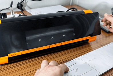
Here is an exemple blind hole:

Why Blind Hole Measurement Is Challenging?
You will face these features constantly in precision manufacturing, specifically with applications like threaded inserts, dowel pin locations, and bearing housings.
Because tool pressure changes near the bottom of the cut, these holes are notorious for geometric errors.
It is not enough to simply check the diameter at the top, you must often verify the roundness, taper, and actual depth to ensure components like hydraulic valves fit their mating parts without bottoming out prematurely.
Most machining processes leave a slight barrel shape or taper right at the end, and standard gauges often “bottom out” before detecting these geometric errors.
You cannot access the feature from the “other side” because there is no other side. This physical constraint traps air, limits coolant flow, and makes inserting measurement probes much harder.
Traditional Blind Hole Gauge Methods
Measuring a blind hole with traditional tools is like parking in a dark garage. You can’t see the back wall, so you have to trust your sensors.
Standard tools often fail here because they simply cannot reach the geometric deviations near the bottom.
To solve this, conventional metrology relies on three heavy hitters: modified dial bore gauges, air plug gauges, and split ball probes.
How to Select the Right Blind Hole Gauge
Selecting the correct gauge for a blind hole is trickier than it looks. You cannot simply grab a standard bore gauge off the shelf.
To get reliable data, you must evaluate the nominal diameter, the workpiece tolerance, and specifically the hole depth.
The right pick depends entirely on your workpiece geometry.
If you need to hold ±0.001 mm accuracy, an air plug is often superior due to its non-contact nature and ability to place jets very close to the bottom.
For general sizing on larger holes, a dial bore gauge is your workhorse. But you need to make sure your probe matches the transmission ratio of your display unit (often 1:1 or 1:2.5).
If these don’t align, your measurement isn’t just slightly off. It is mathematically wrong.
Measurement Procedure & Calibration
Getting accurate numbers isn’t just about owning a fancy gauge. it’s about technique.
Before you even touch the gauge, clean the hole thoroughly. If your blind hole is full of machining oil or chips, your probe contacts won’t sit flush.
Clean both the gauge and the hole using proper metrology cleaning supplies.
For calibration, use a setting ring (or master ring). Insert your probe into the ring and adjust the display to match the ring’s marked dimension.
Be wary of body heat, holding the ring in your hand causes thermal expansion.
When taking the measurement, gently oscillate (“rock”) the handle back and forth inside the hole to find the reversal point. This minimum value represents the true diameter perpendicular to the axis.
Indirect Blind Hole Measurement
Sometimes, traditional hand tools just hit a wall.
Whether the blind hole is too deep, the diameter is too small, or the features at the bottom are too complex, you might find that standard gauges can’t deliver a reliable reading.
In these cases, Impression Material (replication) is the best solution available.
This method involves using replication materials to create a “negative” of the blind hole.
Rather than struggling to insert a mechanical probe into a dark, oil filled cavity, you inject a liquid polymer that flows into every micro feature of the bore.
It cures pretty fast and stays flexible enough to get extracted. Well, to be exact, the final hardness is completely configurable. But in the end, you get a high accuracy (micron) replica of the internal geometry AND surface condition.
The biggest advantage? Total access.
Since the material starts as a liquid, it naturally flows to the absolute bottom of the blind hole, capturing the radius, the corner geometry, and any taper that traditional gauges miss due to their mechanical clearance requirements.
Once polymerized, you extract the solid replica and measure it externally using standard laboratory tools like optical profile projectors, vision systems, or laser scanners.
This technique turns a difficult internal measurement into a simple external one.
It effectively eliminates the “blind” aspect of blind hole measurement, providing you with a permanent 3D record of the bore’s condition, including surface finish and defects, with micron level resolution.
Using Plastiform to Measure Blind Hole Geometry
Using Plastiform impression materials requires a simple standardized workflow.
Follow these steps to ensure maximum accuracy:

- Prepare the Surface: Clean the blind hole thoroughly with a degreaser (like DN1 Cleaner) to remove all pollutants and oil. The surface must be dry for the replica to capture the microstructure accurately.
- Select the Right Product: For blind holes, choose a flexible or semi-flexible cartridge (such as F20 or F50). These allow you to extract the impression even if there are slight undercuts or threads inside the bore.
- Inject the Material: Place the mixing nozzle tip at the very bottom of the blind hole. Inject the Plastiform while slowly withdrawing the tip. This “bottom-up” filling technique prevents air pockets from getting trapped in the critical corner areas.
- Let it Cure: Allow the material to cure. This typically takes 2 to 8 minutes depending on the specific product grade. Do not touch the material during this phase.
- Extract the Replica: Once cured, pull the impression gently out of the hole. The material’s elasticity allows it to release from the walls without damage, returning to its original shape instantly.
- Measure the Replica: Mount the extracted replica on a fixture. You can now measure the diameter, cone angle, and bottom radius using a non-contact system like a profile projector or a laser micrometer.
Blind Hole Measurement Methods Compared
| Measurement Method | Best For | Accuracy | Bottom Clearance | Cost |
|---|---|---|---|---|
| Plastiform Replication | Complex geometry, bottom radiuses, hidden details | High (±1 µm) | Zero (Measure full depth) | Very Low |
| Air Plug Gauge | High-volume production, tight tolerances | Very High (±0.5 µm) | < 1 mm | High |
| Dial Bore Gauge | General shop floor inspection | Moderate (±4 µm) | ~3-5 mm | Low |
| Split Ball Probe | Small diameters (<10mm) | High (±2 µm) | ~1-2 mm | Moderate |
| CMM Probe | Automated inspection of large parts | High (±2 µm) | Limited by stylus ball | Very High |
Advanced Blind Hole Measurement Methods
While Plastiform handles the complex geometry replication, other advanced methods exist for automated workflows.
CMM Probing
Using a Coordinate Measuring Machine (CMM) is the standard for automating deep hole inspection.
You usually have two main strategies here: touch-trigger probing or scanning probing. This creates a highly accurate 3D cylinder model.
But physics still applies.
You are limited by the stylus length and the shank combination. If the probe is too short, you can’t reach the bottom. If it’s too long, you introduce flex/runout errors.
Also, measuring the exact corner where the wall meets the floor is deceptively complex because the probe ball radius often prevents contact with the very bottom edge.
Conclusion
We looked at the main players in this field:
- Impression moulding technique for total geometric characterization.
- Dial bore gauges for broad versatility,
- Air plug gauges for fast precision,
Each method handles the closed bottom differently.
The important thing here is that success comes down to geometry matching.
You need to select a strategy that is specifically designed to measure right up to the hole bottom without hitting the end wall prematurely.
If your probe setup doesn’t account for the necessary bottom clearance, you will likely miss taper or form errors hiding deep inside the part.
For highly demanding applications, I always recommend verifying your results with a complementary method to cross-check your results.
Establishing a standardized workflow is the best way to protect yourself from nasty surprises in production!
Frequently Asked Questions
What defines a blind hole in mechanical engineering?
A blind hole is a milled or drilled cavity that does not break through to the other side of the workpiece. It has a distinct bottom or closed end. This design creates specific measurement challenges. You cannot use standard through-hole tools because they often require the probe to pass completely through the part to get a reading.
Why is measuring a blind hole more difficult than a through hole?
The main issue is limited access. Standard bore gauges usually have a guide tip that hits the bottom before the measuring contacts reach the end. This leaves a dead zone at the bottom where you cannot get a reading. Also, debris like metal chips and coolant often settle at the bottom and interfere with your measurements.
Which tools are best for measuring blind hole diameters?
You typically use dial bore gauges with specific blind-hole anvils, air plug gauges, or split ball probes. Dial bore gauges are versatile for general shop use. Air gauges are excellent for high-precision batch inspection because the air jets sit very close to the bottom edge of the tool. Split ball probes are useful for smaller diameters.
How do you accurately measure the depth of a blind hole?
You need a depth micrometer or a caliper with a designated depth rod. Place the base of the tool firmly on the reference surface and lower the rod until it touches the bottom. Be careful with drill points. Most engineering drawings specify depth to the full diameter (the shoulder), not to the tip of the drill cone.
What is the minimum measuring distance from the hole bottom?
This depends on the specific gauge design. Standard internal micrometers might stop several millimeters short of the end. Specialized blind-hole bore gauges or air plugs have measuring contacts positioned much closer to the front face. Some high-end split ball probes allow you to measure within 1 millimeter or less from the bottom of the bore.
Why are air plug gauges preferred for high-volume blind hole inspection?
Air gauges use back-pressure to measure size without heavily contacting the surface. For blind holes, manufacturers can place the air nozzles very close to the plug tip. This lets you inspect the diameter right at the bottom where taper often occurs. They are also self-cleaning because the continuous air flow blows away minor coolant or dust.
What geometric errors commonly occur at the bottom of blind holes?
You often find taper or barrel shapes due to tool wear or chip clogging during machining. The drill or boring bar might deflect as it reaches the bottom of the cut. This creates an oval or conical shape that standard gauges might miss if they cannot reach deeply enough into the cavity to detect it.
How should you calibrate a bore gauge for blind hole measurement?
You must use a calibrated setting ring that matches your nominal diameter. Zero the gauge inside this ring before use. Since blind hole gauges often have shorter guide mechanisms, make sure the gauge is perfectly perpendicular to the ring axis during calibration. This prevents cosine errors when you transfer the gauge to the workpiece.
When should you use impression materials for blind hole measurement?
Use impression testing when the hole is too small, deep, or complex for physical probes. You inject a silicone rubber compound into the hole to create a precise negative replica. Once it cures, you remove the replica and measure it using an optical comparator or vision system outside the restricted space. This captures the exact geometry of the blind bottom.