Last updated:
Ultrasonic Testing is a non-destructive method using high frequency sound waves to inspect the internal structure of a material without damaging it.
It operates like a medical ultrasound for industrial components, sending sound pulses into a part and analyzing the returning echoes to find flaws or measure thickness.
To confirm a weld is solid all the way through or measure a pipe’s wall thickness from the outside, for exemple, it’s an ideal solution.
In this article, I’ll explain how Ultrasonic Testing works.
We will go through its primary purposes for flaw detection, thickness measurement, and material characterization and why it’s adopted in the aerospace, oil and gas, and transportation industries.
Then, I’ll try to present you the equipment, techniques, advantages, and limitations of this powerful inspection technology.
Ready to dive in?
Table of Contents
What is Ultrasonic Testing?
Ultrasonic Testing (UT) is a non-destructive testing (NDT) method that use industrial grade ultrasounds to ensure a part doesn’t contain hidden cracks or invalid thickness.
The basic idea is to send very high frequency sound waves through a material (a pipe for exemple) to find hidden problems without causing any damage.
These sound waves have frequencies far above human hearing, between 0.1 and 15 megahertz (MHz), but can sometimes go as high as 50 MHz.
The core principle is simple.
A device sends a pulse of sound into the part you are inspecting. If the sound wave travels through and finds no issues, it behaves in a predictable way.
But if it hits a crack, a void, or a change in the material, some of that sound energy bounces back as an echo. By analyzing these returning echoes, a technician can locate flaws hidden inside a component.
This ability to inspect the entire volume of a part makes it a very powerful strategy against other methods.
Techniques like Plastiform replicas, liquid penetrant or magnetic particle testing are excellent for finding defects on surfaces but cannot see what’s happening internally.
Controls using Ultrasounds gives you a view beneath the surface.
To maintain consistency, technicians use a standardized vocabulary for test results and equipment, which is outlined in the ASTM E1316-23 standard.
Another advantage is safety.
Unlike radiographic testing that uses X rays, the high frequency sound waves in UT are completely harmless to operators.
This allows inspections to happen in busy work areas without the need for special safety precautions related to radiation.
Which is a huge plus for industrial factories.
How Does Ultrasonic Testing Work?
Ultrasonic Testing is kind of a type of industrial sonar.
As I said in the previous chapter, All you do is you send high frequency sound into a part and then analyze the returning echoes. These echoes create a picture of what is happening inside the material. This method reveals hidden flaws or measures thickness without causing any damage to the component.
A typical inspection system contains a few elements:
- A Transducer, which is the part you place against the material.
- A pulser/receiver creates and listens for electrical signals. It sends a high voltage pulse to a transducer.
- A special piezoelectric crystal inside the transducer vibrates from the electricity, creating the sound wave.
When echoes return, the crystal converts the sound back into an electrical signal, which appears on a display for analysis.
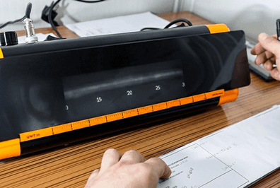
On the display screen, returning echoes appear as peaks.
The height, or amplitude, of a peak represents the intensity of the reflection, giving an idea of the reflector’s size.
The peak’s position along the time or distance axis shows how long the sound took to travel. From this transit time, a technician can calculate the precise depth of a flaw.
This is the basic setup you’ll be using, but there are multiple types (or “sub technology”).
Pulse-Echo
In this setup, a single transducer acts as both the speaker and the microphone.
It directs a short burst of sound into the part and then listens for reflections. An echo will bounce back from the material’s far side, known as the “back wall“, or from any internal discontinuity like a crack.
This is a very practical way to perform the tests because you only need to access one side of your component : no need to move or dismantle the part to test.
A good plus for industries like Oil and Gas in which pipelines are very large and difficult to move.
Through-Transmission
This approach uses two separate transducers.
One sends sound from one surface, and a receiver on the opposite side listens for it.
If a flaw exists between them, it will block or weaken the sound. The receiver then picks up a weaker signal or no signal at all.
Couplants
Air is a poor medium for transferring high frequency sound. If you place a dry transducer on a metal surface, most of the sound energy reflects off the surface.
To get good sound transfer, you need a liquid couplant.
This is usually a gel, oil, or water that fills the tiny air gaps between the transducer and the test piece.
Some modern techniques do not require a couplant. Methods like Electromagnetic Acoustic Transducer (EMAT) or laser excitation generate sound directly within the part.
These are great for inspecting very hot, rough, or fast moving objects where using a liquid couplant is not possible.
Sound Wave Interaction with Materials
When a sound wave hits a boundary with a different material, some of it bounces back.
This is reflection.
It happens because of a property called acoustic impedance, which is related to a material’s density and the speed of sound within it.
A large difference in acoustic impedance, like between steel and air, causes a strong reflection. This is why a crack shows up clearly.
If a sound wave hits a boundary at an angle, it changes direction as it enters the new material.
This bending is refraction (the same effect that makes a straw look bent in a glass of water).
This principle, described by Snell’s Law, is used to steer sound beams into areas that are not directly beneath the transducer, such as the angled faces of a weld.
Not all of the sound reflects or refracts at a boundary.
Some of the sound energy continues through the new material.
This is penetration.
The goal of an Ultrasonic Inspection is to balance reflection and penetration so that you can find defects throughout the material without losing the sound signal.
Wave Modes Used in UT
Operators can select different types of sound waves, or wave modes, for an inspection.
Each mode causes the particles in the material to vibrate in a distinct way.
These different vibrations have unique characteristics for finding specific kinds of defects.
Here is a list of those different types of vibrations:
- Longitudinal Waves, also called L-waves: The particles move back and forth in the same direction that the wave is travelling.
These are the fastest sound waves and can pass through solids, liquids, and gases. They are commonly used for thickness measurements. - Shear Waves, or T-waves: The particles vibrate perpendicular to the direction of wave travel. Shear waves only travel through solids and move more slowly than longitudinal waves.
Their high sensitivity to small reflectors makes them very effective for inspecting welds. - Surface waves, known as Rayleigh waves: They travel along the surface of a part, much like ripples on water.
Their energy is concentrated in a very shallow layer near the surface. This makes them perfectly suited for finding very small cracks that break the surface. - Plate waves, often called Lamb waves: Technicians use them for inspecting thin materials like metal sheets or composite panels. These waves travel through the entire thickness of the material, guided by its top and bottom surfaces.
They are useful for screening large areas quickly from a single inspection point.
That’s basically the 4 wave modes you’ll see in the real world. The most widely used are L Waves but, as an engineer you should always select the one that fit your needs.
Equipment and Display Methods
To look inside a material with sound, you need the right tools to create the sound, listen for the echo, and display the results.
An ultrasonic testing system is made of a few key parts that work together to turn invisible sound waves into data a QA engineer can actually work with.
Let’s detail a bit further the equipments now we understand what it does.
Pulser, Transducer, and Display
The pulser/receiver is the brain of the operation.
This electronic unit generates a powerful, high voltage electrical pulse. That pulse travels to the transducer, which acts as the system’s mouth and ears.
Inside the transducer is a piezoelectric element.
This special crystal has a great set of characteristics:
- When it gets hit with an electrical pulse, it vibrates rapidly, creating the high frequency sound wave that goes into the part.
- When a returning echo hits the crystal, it does the reverse. It vibrates and generates an electrical voltage. The pulser/receiver then processes this signal for the display screen.
Transducers come in several forms for different jobs.
Single-element transducers are the standard.
Dual-element transducers use separate crystals for sending and receiving, making them great for measuring corrosion on rough surfaces.
Angle beam transducers send sound in at an angle, which is perfect for inspecting welds.
Phased array transducers contain many small elements that can be pulsed individually to electronically steer the sound beam, giving you more control and better imaging.
As you can see, its like picking a wave. It depends on your needs.
A-scan, B-scan, and C-scan
Once the system receives an echo, it needs to be displayed in a way an operator can interpret. There are three common formats.
The A-scan is the most fundamental display.
It’s an X-Y grid that looks like a graph :
- The horizontal axis represents the time it took for the sound to travel, which relates to the distance into the material.
- The vertical axis shows the amplitude, or strength, of the returning echo. A tall peak popping up on the screen signifies a reflector (a flaw or the back surface of the part).
A B-scan provides a profile or cross sectional view.
As you move the transducer along the part, this display shows the depth of reflectors and their length along the scan path.
It gives you a 2D look at the material’s internal structure.
A C-scan offers a top down, bird’s eye view.
It maps the results over the inspection area, showing the shape and size of flaws as if you were looking down on them.
This produces a detailed image of any hidden discontinuities.
The reliability of these displays depends on the instrument performing correctly.
The standard practice for checking the performance of these tools is outlined in ASTM E317-21. This document provides methods to verify that the equipment is working as expected.
Common Ultrasonic Testing Techniques
We have seen so far that there are always several options available to you, whether it be for equipment, wave types or strategy.
To get sound waves into a material for inspection, technicians choose, once again, from several methods. This choice depends on the part being tested, the environment, and the type of flaw they are looking for.
What a surprise, isn’t it ?
The main approaches are grouped into three categories: contact testing, immersion testing, and air-coupled testing.
Contact testing is the most common method, where a probe is placed directly on the component’s surface. A gel or liquid (the couplant), is applied between the probe and the part to help transmit the sound energy without any air gaps.
Very similar to how a doctor would proceed ultrasounds to a pregnant woman.
Straight beam, angle beam and surface wave, that we’ve seen at the beginning of this article, all fall within this category of tests.
For immersion testing, the component is submerged in a tank of water. The probe also enters the water, but it does not touch the part.
The water acts as a perfect medium, carrying the sound from the probe into the component. This is very effective for inspecting parts with complex geometries and curved surfaces, as it guarantees consistent sound transmission. Immersion UT is usually performed in a laboratory
Air-coupled testing is a specialized technique that uses air as the medium to transmit the sound waves. This non contact method is perfect for materials that could be damaged or contaminated by liquid couplants, such as certain composites found in the aerospace industry.
Advanced UT Techniques
There is also less common techniques you might need to know about.
Phased Array Ultrasonic Testing (PAUT)
Phased Array Ultrasonic Testing (PAUT) uses a probe with multiple small elements.
A computer controls these elements to steer and focus the sound beam electronically, creating detailed cross-sectional images, much like a medical ultrasound.
The performance of these systems can be verified using guides like ASTM E2491-13(2018).
Time of Flight Diffraction (TOFD)
It uses two probes, one sending and one receiving.
It is highly sensitive for sizing flaws because it measures the time it takes for sound waves to bend, or diffract, from the very tips of a defect.
This provides very accurate height measurements for cracks.
Full Matrix Capture (FMC) & Total Focusing Method (TFM)
Those combined methods represents a powerful technology advancement:
- FMC captures all possible data from a phased array probe.
- TFM uses this data with software to produce a perfectly focused image at every point within the inspection area.
It’s a very effective way to get a clear picture of a flaw’s size and location.
Electromagnetic Acoustic Transducer (EMAT)
Another non contact technology.
It generates ultrasonic waves directly within a conductive material using interacting magnetic fields, completely avoiding the need for a couplant.
This makes EMAT a good technique for high temperature and high speed automated inspections.
Guided wave testing
Last but not least, it is used to inspect large structures like pipelines over long distances from a single point.
It sends sound waves that travel along the component’s structure, making it possible to detect corrosion and other defects in hard to access (or impossible to access) areas, such as buried pipes.
Interpreting the complex signals from this technique requires specialized training.
Limitations of Ultrasonic Testing
While ultrasonic testing is a powerful method, it is not a perfect match for every inspection challenge.
It comes with a set of limitation.
The Need for Expertise and Preparation
First, the results are only as good as the person running the test.
An experienced technician is required to perform the inspection and correctly interpret the data.
It requires a strong training to be able to tell the difference between signals that indicate critical flaws and those coming from the part’s geometry or acceptable internal structures.
The equipment also requires precise preparation.
Before an inspection, the system must be calibrated using reference standards. These are special blocks with known defects that provide a baseline for what a real flaw might look like.
Without these standards, flaw characterization becomes unreliable.
Even with a skilled operator, false positives can happen.
Sometimes the shape of a component creates reflections, or spurious signals, that look like defects.
Distinguishing these from actual problems demands a high level of training and experience from the person performing the inspection.
Material and Surface Constraints
The condition of the part’s surface is also a factor to pay attention to.
For sound to travel from the probe into the material, the surface must be relatively smooth and clean. Any loose scale, rust, or paint must be removed to get a clean signal.
Properly bonded paint may sometimes remain.
Conventional testing also needs a couplant, like a gel or liquid, to bridge the microscopic air gaps between the probe and the part.
While necessary, this can be messy and challenging on certain job sites. This step is not needed for non-contact methods like EMAT or laser UT.
Some materials and shapes are difficult to inspect.
Parts that are very rough, irregularly shaped, exceptionally thin, or very small can be problematic.
Materials with a coarse grain structure, such as cast iron, scatter the sound waves for exemple.
This creates high signal noise and makes it hard to find true defects.
Technical and Equipment Hurdles
The orientation of a flaw can make it invisible.
A defect lying parallel to the path of the sound beam may not reflect any energy back to the probe. This means it can go completely undetected during the scan.
And, finally, the cost of the equipment can be a consideration.
Professional ultrasonic instruments and the specialized probes needed for different applications represent a significant financial investment. It is often out of consideration for many small, medium and even some large companies.
Industry Applications and Standards
Ultrasonic testing is widely used among the most demanding industries.
Its ability to find defects deep inside a material makes it a trusted tool for quality control and safety checks from massive power plants to delicate aircraft components, UT provides valuable informations without causing any damage.
In the energy sector, technicians use UT for inspecting pressure equipment, piping, and new welds.
It helps assess corrosion damage and detect cracks that form during service.
The pipeline industry relies heavily on UT for the quality of girth welds. The API 1104 (22nd Edition) is a document that accepts advanced methods like PAUT and TOFD as powerful alternatives to traditional radiography.
You will also find UT in aerospace for checking landing gear and engine components. In transportation, it inspects rail tracks and axles for fatigue. For infrastructure, it verifies weld quality on steel beams.
Even the medical field uses this technology for diagnostic imaging because it does not involve ionizing radiation.
Standards for Ultrasonic Testing
You’ve seen how ultrasonic testing works, from sending sound waves with a transducer to interpreting the echoes on a display.
We have covered different techniques like pulse-echo and advanced methods including PAUT, showing its value across aerospace, manufacturing, and energy industries.
To perform these inspections safely and consistently, engineers depend on standards.
These documents provide the common procedures and acceptance criteria needed for reliable results.
It is good to remember that many of these standards are adopted at a state or national level. This often makes compliance a mandatory part of commercial and industrial contracts, turning these guidelines into legal requirements.
This collection of standards is updated regularly to reflect new technology and findings. It’s your role as a method engineer to select the good standard to perform the tests on your parts/production.
Conclusion
We have seen the fundamentals of ultrasonic testing, showing how this non-destructive method uses high-frequency sound to look inside materials.
Its ability to detect internal defects and measure thickness makes it a modern and efficient quality control tool.
From aerospace to manufacturing, a wide range of industries depend on Ultrasonic inspections.
The technique provides data for making informed decisions about the safety and reliability of components, structures, and systems.
The technology has progressed far beyond simple pulse-echo methods.
Advanced techniques like Phased Array (PAUT), Time of Flight Diffraction (TOFD), or Full Matrix Capture (FMC) now offer incredibly detailed imaging capabilities.
But be aware,
Executing these inspections correctly requires highly trained technicians who follow strict industry guidelines. It requires a strong understanding of the science and the equipments behind the data and cannot be used in all situations.
It’s also a very expensive instrument that requires a huge budget and needs.
The proper application of ultrasonic testing is a direct investment in safety and performance. It helps prevent failures in mechanical engineering applications, which protects personnel and extends the operational life of valuable assets.
Frequently Asked Questions
What is ultrasonic testing in simple terms? It’s a method that uses high frequency sound waves, similar to a medical ultrasound, to see inside a material without damaging it. These sound waves travel through the part and bounce back from internal flaws or the back surface, revealing hidden defects.
Why is it called “non destructive”? It is called non destructive because the inspection process does not harm or alter the part being examined. You can test a component and then put it right back into service if no defects are found.
Is ultrasonic testing safe for people? Yes, the high frequency sound waves used in this method are harmless to operators and anyone nearby. This is different from other methods like radiography, which use ionizing radiation.
What common problems can ultrasonic testing find? This technique is excellent for finding internal issues like cracks, voids, and porosity deep inside a material. It is also very accurate for measuring the thickness of a material, for example, to check for corrosion.
Do you need to prepare the surface before testing? Yes, the surface must be clean and smooth enough for the sound waves to enter the material properly. Loose paint, rust, or heavy scale must be removed before inspection.
Can you use it on any material? It works best on dense, uniform materials like metals, plastics, and composites. Materials that are very coarse, like certain cast irons, or very soft can be difficult to inspect because they scatter or absorb the sound waves too much.
How do you choose between pulse echo and through transmission techniques? You use the pulse echo method when you only have access to one side of the part, which is the most common approach. Through transmission, which requires access to both sides for separate sending and receiving probes, is typically used for materials that heavily weaken sound waves.
What is the role of acoustic impedance in ultrasonic testing? Acoustic impedance is a material’s resistance to sound passing through it. When sound waves hit a boundary between two materials with different acoustic impedances, like steel and air in a crack, some of the sound energy is reflected back. This reflection is what allows us to detect the defect.
When would you use shear waves instead of longitudinal waves? Shear waves are typically introduced into a part at an angle and are very sensitive to discontinuities that are not parallel to the surface. This makes them highly effective for inspecting welds for defects like lack of fusion or cracks along the fusion line.
What’s the main difference between conventional UT and Phased Array UT (PAUT)? Conventional UT uses a probe with a single crystal that sends a sound beam in one direction. Phased Array UT uses a probe with many small elements that can be pulsed individually. This allows the sound beam to be electronically steered and focused without moving the probe, creating detailed images similar to a cross section of the part.
Why are reference standards required for ultrasonic inspection? Reference standards, which are blocks of material with known manufactured defects, are used to calibrate the equipment. This calibration establishes a baseline for the inspection, allowing the technician to accurately determine the location, size, and type of a flaw found in the actual component.