Last updated:
Hydrostatic testing is a non-destructive quality control method used in engineering to verify the structural integrity and leak-tightness of pressure vessels, pipelines, and other systems.
It involves filling the component with an incompressible liquid (usually water) and applying a controlled internal pressure around 1.25 to 1.5 times the maximum allowable working pressure.
Sounds simple, right?
But here’s where it gets interesting.
Hydrostatic testing gives us a reliable way to check strength and performance. Everything is measured, repeatable, and safe. It is also a safer way to make sure a pipe system is safe than pneumatic testing.
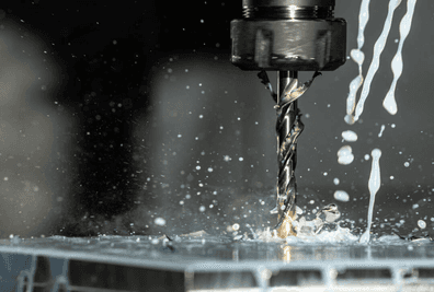
If you press down on a plastic ruler with your hands, you can see it bend. That is a basic test of flexure, or bending.
Same thing with hydrostatic testing : The pump makes pressure, the part squashes or bends, and instruments record what happens.
Table of Contents
What is Hydrostatic Testing ?
Hydrostatic testing is a simple way to prove that a pressure containing item can handle its load and doesn’t leak.
You fill it with liquid and pressurize it to a code specified value to show it’s strong and tight before use or after changes.
The process is simple in concept.
Fill the system with liquid (commonly clean water), purge trapped air, then use a hydrostatic test pump to pressurize the test section to a specified test pressure.
The target pressure depends on the governing code and equipment type.
How does it work?
A pumping unit, generally called a hydrostatic test pump, pushes liquid into the pipeline or test stand.
Raise pressure at a gentle, controlled rate using the pump.
Once you reach the target, isolate the pump with a closed valve and only add small top ups if needed. Increase pressure in steps (about 25%, 50%, 90%, then full), pause to check for leaks, and open/close valves slowly to avoid water hammer.
Hold at pressure for the time desired (often between 10 up to 60 minutes). Use recently calibrated gauges sized so the test pressure is near mid scale, and record both pressure and temperature.
Any pressure change is evaluated with temperature compensation. Passing means no leaks and pressure behavior within code limits.
It uses liquid rather than compressed gas, which is generally safer because liquids are nearly incompressible (but it is not risk free), failures can still be violent, so exclusion zones and controls are required.
This makes it safer than pneumatic testing, and often used instead for that reason.
If a pipe fails under liquid pressure, the stored energy is released “slowly” compared to compressed air, which can cause violent explosions. That safety factor is why hydrostatic testing is the standard in most critical applications.
Where is hydrostatic testing used?
Hydrostatic testing is used in many industries and situations :
- Before commissioning: to prove new piping, pipelines, vessels, and components are strong and leak tight before going into service.
- After repairs or modifications: to confirm that welds, fittings, or replaced sections will hold under working conditions.
- On tanks, pressure vessels, heat exchangers, cylinders, and valve bodies: check the pressure boundary is strong and leak‑tight.
- In facilities with high safety standards: wherever pipes and storage systems must prove their reliability before use.
As for the industries, the most common ones include:
- Oil and Gas: pipelines, storage tanks, valves, and pressure vessels
- Power Generation: boiler drums/headers, condenser water boxes, and safety related plant piping.
- Chemical and Petrochemical: process piping, reactors, and storage vessels
Every one of these fields uses hydrostatic testing to verify that systems can safely handle the pressures they’ll see in service.
It’s a common, lower‑risk way to show pressure equipment is both strong enough and leak‑tight before service or after changes.
Core Components of a Semi‑Automatic Hydrostatic Power Pack
A semi‑automatic hydrostatic power pack is the most common gear of many testing setups.
It provides controlled pressure, steady pacing, and built‑in safety features that make testing reliable day after day. Let’s break down the key parts and see how they work together.
Dual‑Stage (two‑speed) Pump Setup
The heart of the system is a dual‑stage (two‑speed) setup.
A high flow fill stage and a high pressure stage:
- First stage is a high flow, low‑pressure pump. Its job is to fill fast until a preset switchover pressure, well below the test pressure.
- Second stage is a low delivery, high pressure pump with controlled output via a variable speed drive or a bypass/regulator.
Why split it like this?
Because you want speed while you’re just filling, and tight control once the system is under pressure.
The pack switches from fill to high pressure automatically at the switchover pressure to avoid spikes, and check valves stop any back flow between stages.
“Semi‑automatic” means you set the target pressure and ramp rate and hit start.
The controller handles the ramp, cuts off at the point you set, logs the data, and triggers the alarms (or shutdowns) if limits are exceeded.
The dual‑stage setup saves time and still gives fine control when applying the load. Operators often say this blend of speed and precision is exactly what makes the machine feel “right” in use.
Motor and Power Requirements
An AC (Alternating Current) motor drives the pump.
Typical specs:
- Power: small bench packs run ~500–1000 W on single phase power. larger skids often need 2–15 kW (three phase). Pick motor size to match your required flow and test pressure.
- Voltage: Single phase 120/230 V for small units. Three phase 380–480 V for higher power rigs. Check phase, frequency, and current draw on the nameplate.
For small single phase packs, installation is usually plug‑and‑play with proper grounding. Bigger units may need a dedicated breaker, three phase supply, and local electrical approval.
Manifold and Overpressure Protection
Liquid flow is managed through a manifold, which also includes two key protections:
- A pressure relief valve (PRV), that limits maximum pressure, set just below the safe limit.
- A fast dump/vent valve that lets you safely bleed off pressure quickly (to depressurize quickly).
Think of the PRV as the steady guard at the door, and the dump/vent valve as the quick responder when you need pressure gone now.
Together, they protect the machine, the test section, and the component.
Liquid Tank and Monitoring
A tank stores enough hydrostatic liquid to keep the system stable over repeated runs. You’ll want clear level and temperature indicators, plus a suction strainer and a return filter so the fluid stays clean.
A quick glance at the sight glass and gauges is all it takes before you start.
The recommended liquid is clean water (often with a rust inhibitor, oxygen scavenger and glycol mix if freezing is a risk), depending of your industry and if your tested component is subject to contamination.
In larger field applications such as pipeline or facility pressure testing, hydrostatic power packs are paired with external water sources to keep up with the higher test volumes. The principle is the same, but the setup scales to match the length and capacity of the system under test.
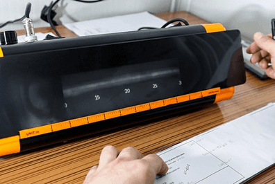
Load Readout and Instrumentation
Load data is displayed on a battery powered digital gauge. It takes the pressure from the transducer and converts it to a load value.
The transducer in the pack measures pressure, and the unit shows the applied load in simple digital numbers.
Because the readout is battery powered, it doesn’t need extra cabling to the mains. This makes it especially practical when frames are moved around the floor or when testing needs to be done in temporary setups.
Mobility and Integration
The power pack can usually be supplied as a standalone unit. With the right equipment set, it can be mounted on wheels or a cart so it can move easily between test stations.
This flexibility seems like a small detail but makes a big difference in day‑to‑day quality of life for the teams running the tests.
What is Pace Rate Control ?
In hydrostatic testing, control over the pace of pressurization is just as important as the maximum pressure itself.
A pace rate control valve sets how quickly the system moves from filling to full test pressure, and then keeps that speed consistent until the hold period.
Why does that matter?
Because if pressure rises too quickly, it can cause water hammer, damage seals, or give you misleading results.
Controlled pressurization prevents those spikes and ensures the readings at failure or during hold time are trustworthy.
Safety and Reliability
Two key safeguards support this process: a pressure relief valve (PRV) to prevent over pressure, and a dump/vent valve to let you release test pressure quickly if needed.
Together, they protect the system, the test piece, your gauges, and, most importantly, the people around the test. That protection is not just about hardware cost, it also avoids failed tests, repeating the work, and questionable data.
A stable hydrostatic circuit also keeps unwanted heat in check. Larger reservoirs help absorb heat, and pumps are sized so that even during long or repeated runs, the system stays in a safe temperature range.
Early warning from the temperature gauge gives operators time to adjust conditions before performance drifts.
Selecting Between Manual, Semi‑Automatic, and Automatic Setups
Hydrostatic testing setups come in three main levels of control:
- Manual, which are powered by a hand operated pump. Simple, portable, and useful for training, quick checks, or occasional jobs where speed is not critical.
- Semi‑Automatic, as introduced earlier, uses a motorized power pack with valve based pace control. Less complex than a full console, more consistent than manual. It’s a common choice when testing is regular but not overwhelming.
- Automatic, has a dedicated control unit that fully manages load, pace rate, and data. Best for large series of tests or when strict standards demand push‑button repeatability.
Each has a place.
Manual suits low volume or field mobility.
Semi‑automatic hits the balance between control and simplicity.
Automatic fits high volume or compliance‑driven operations.
This choice depends on your very application but all options are available.
Setup, Operation, and Maintenance Basics
Getting a power pack ready is straightforward, but a few steps always matter.
Setup Checklist
Here’s a quick and relevant list of elements to double check before running a test:
- Electrical supply: Single phase connection, either 220–240 V at 50–60 Hz or 110–120 V at 60 Hz depending on the model. Confirm grounding and run the motor briefly without load to check rotation and listen for irregular sounds.
- Test fluid level: Fill the pack’s hydraulic side with the specified fluid. This is just for the power unit itself, not the system under test.
- Test medium for the system: The pipe or vessel under test is normally filled with clean water, sometimes with a corrosion inhibitor.
- Test section or system connection: Secure hoses, connect the pressure transducer, and align the setup.
- Pace rate control: Use the rapid fill stage to get pressure up close to the starting point, then confirm the pressure rise is smooth and within the test method’s limits.
Keeping Operations Safe
The unit should always sit on a flat and stable surface to avoid vibration or tipping when in use.
Before each series, check the liquid level and temperature on the gauge. If the liquid looks foamy, that means there is air in the circuit and this issue needs to be fixed before you continue.
A quick dry run without a real element to test helps confirm that rapid approach and pace control are working smoothly.
After each test, release the pressure slowly using the dump/vent valve, never by cracking a fitting.
Daily Maintenance
Taking care of your equipment daily is simple but makes a big difference.
Keep the working liquid clean, replace it if it shows contamination, and always confirm the level before use.
When water is used as the test medium in pipelines, proper drainage and treatment after testing are part of safe practice. A quick wipe of fittings prevents dirt from entering the system, while monitoring the level and temperature indicators gives early warning if conditions start to shift.
Valves and seals should be inspected every few weeks, and it is a good idea to keep a few basic spares ready in case of leaks or wear.
Key specifications
There isn’t a single set of specs that fits every hydrostatic power pack.
What matters is matching the numbers to the job you’re doing. In labs, a few hundred bar of pressure with a small motor and tank might be more than enough.
For larger systems like pipelines, you’ll need higher capacity pumps, access to external water tanks or trucks, and bigger power sources to move the extra volume.
The same applies to design details.
Dual stage pump setups give you both speed and control, while a relief valve (with a dump/vent valve) is essential no matter the size.
Readout options range from a simple digital display to full data logging, depending on how strict reporting needs to be.
Don’t look at these specs as fixed.
Think of them as levers you adjust based on scale, duty, and environment, as you would in any scenario, because at the end of the day, engineering is all about making the right choices for the specific problem you’re solving.
Types of Hydrostatic Tests
These tests usually come down to two main purposes: strength and leak tightness.
A strength test pushes the system above its normal operating pressure, often about 1.5 times higher, to prove that it can safely handle extreme conditions.
The goal isn’t to run it until failure but to show the material or system won’t deform, crack, or burst under load.
A leak test, on the other hand, focuses on tightness. After the system is pressurized, it is held at a steady level for a set period of time, sometimes just 30 minutes in small cases, or up to 24 hours for large pipelines or vessels.
If the pressure stays constant, it passes. If it drops, there’s a leak that needs to be tracked and fixed. In the real world, both tests often go together: first you prove the strength, then you check for leaks.
Standards and Regulations
a Hydrostatic test isn’t just about good practice, it’s about following the rulebook. Different industries lean on different standards to define the pressure, hold times, and pass/fail criteria.
For example, ASME B31.3 covers process piping, API RP 1110 applies to liquid pipelines, and ASME Boiler and Pressure Vessel Code guides pressure vessels. At a global level, ISO standards help align requirements across borders.
There are many other codes. Please refer to ASME and API or any other list of documents for reference.
The exact document depends on the system and location, but the intent is always the same: create reliable and consistent results based on a strong standard.
In most projects, inspectors or clients will ask for test records or even full data logs to verify that a hydrotest was performed according to code.
Hydrostatic Testing vs Pneumatic Testing
A common question is why hydrostatic (liquid based) testing is preferred over pneumatic (gas based) testing in most cases.
The answer is safety.
Liquids like water are nearly incompressible, which means they don’t store much energy under pressure. If something fails, the energy released is limited compared to compressed gas.
Gas, on the other hand, compresses like a spring. If it bursts, the release is violent and can seriously damage equipment or injure anyone nearby. It can destroy your whole component and be very dangerous for the operators.
That’s why pneumatic testing is only used in special cases where liquid isn’t practical, and even then strict precautions are taken.
For almost everything else, hydrostatic testing with water is the safer and standard choice.
Common Challenges in Hydrostatic Testing
Even with the right equipment, a few challenges often show up during hydrostatic tests.
Air pockets are a common one.
If air is trapped, the pressure will behave unpredictably and the test results can’t be trusted.
More importantly, trapped air can release energy dangerously if the system fails. Careful venting before the test solves this.
Another challenge is pressure drift. Over the hold period, you may notice the pressure slowly changing. Common causes are temperature shifts, small leaks at fittings, or the system settling as materials strain and relax.
Either way, it makes consistent monitoring important.
On longer duty cycles, heat build up can also be an issue.
This mostly comes from the pump working at high pressure. A stable fluid circuit, the right liquid grade, and clear temperature indicators help keep things predictable and give early warning before it drifts out of range.
Conclusion
Hydrostatic testing is a proven way to demonstrate that pressure equipment is both strong and leak‑tight. This testing strategy is used across industries including oil and gas, power generation, and chemical plants and typically is used before commissioning, after repairs, and during periodic inspections.
It works by filling a test frame with liquid (usually clean water), venting out the air, and raising pressure under control until the code specified test value is reached.
Semi‑automatic power packs with dual stage pumps allow fast filling and then precise pressurization, making the process efficient and safe. Motors, manifolds, relief valves, dump valves, tanks, gauges, and filters all play a role in controlling pressure and keeping the circuit reliable. Pace rate control prevents pressure shocks and water hammer, while calibrated instruments make the results repeatable.
Hydrostatic testing is guided by standards such as ASME, API, and ISO, which define test pressures, hold times, and acceptance criteria.
Compared with pneumatic testing, hydrostatic testing is safer because water stores very little energy, but it still requires exclusion zones and venting for safety.
Each test section is brought to pressure gradually, held for the specified time, and accepted if there are no leaks and the pressure behavior is within code limits.
Questions & Answers
Why is water the main medium for hydrostatic testing?
Water is cheap, widely available, and nearly incompressible. That means if something fails, there is very little stored energy compared to compressed gas, so the release is far less violent. Corrosion inhibitors or glycol are sometimes added depending on weather, materials, and project requirements.
It also have the advantage of limiting the contamination on the part to be tested.
When is pneumatic testing used instead?
Pneumatic testing is only chosen when water cannot be used, for example if the system cannot be dried afterward or if contamination would make water unsuitable. Because compressed gas stores large amounts of energy, these tests are much more dangerous and can only be run with strict extra precautions.
How much higher is the test pressure compared to normal operation?
Most codes require between 1.25 and 1.5 times the design or maximum allowable pressure. The exact factor depends on the equipment type, the standard being applied, and the material’s allowable stress at test temperature. This ensures enough margin to prove strength without overstressing the system.
What is the most common cause of wrong results?
The biggest issue is air trapped in the system, because it makes the pressure response unpredictable and hides true leaks. Trapped air also increases the stored energy in the system, making a failure more dangerous. Careful venting at high points before pressurization eliminates this problem.
How long is pressure usually held during a test?
Hold times vary depending on the application. Small parts may only be held for 10–30 minutes, while long pipelines or large vessels may require 8, 12, or even 24 hours under pressure. The point is to make sure the system settles and any leaks have time to show.
What records are normally required?
At the simplest level, a test log shows pressure and temperature over time, with notes on any irregularities. On many projects, inspectors demand continuous chart recordings or digital data files. These records prove the test was performed according to code and allow later verification.